


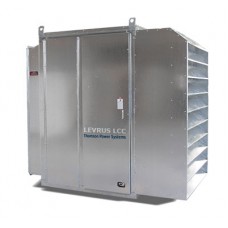

LOAD BANK, TYPE TLB-500H-380V-3-C
Available horizontal configuration options for Thomson Power Systems 400 V:
- TLB-200H-380V-3 - $23,000 including VAT, DDP Moscow;
- TLB-300H-380V-3 - $24,000 including VAT, DDP Moscow;
- TLB-500H-380V-3 - $25,500 including VAT, DDP Moscow;
- TLB-625H-380V-3 - $26,000 including VAT, DDP Moscow;
- TLB-1000H-380V-3
- TLB-2500H-380V-3
Available vertical configuration options:
- LBO-250H-380V-3
- LBO-500H-380V-3
- LBO-625H-380V-3
- LBO-1000H-380V-3
- LBO-2500H-380V-3TECHNICAL DESCRIPTION
Mobile load bank for indoor installation or under a canopy, with a 3-phase 4-wire AC operating voltage. The mechanical construction consists of a standardised galvanised steel enclosure, IP10 (NEMA 1) rated. Load steps and rated parameters are shown in the table below:
Parameter
Value, AC
Model
TLB-500H-380V-3-C
Operating voltage, V
380
Rated current, A
950
Frequency, Hz
50
Operating mode
Continuous duty
Ambient air temperature
from -40 °C to +50 °C
Load control steps
2 x 50 kW
4 x 100 kW
Load elements:
Thomson load banks use patented air-cooled resistors of the registered trademark «cool load»TM”, made from Aluchrom 0 alloy (also known as KANTHAL Alloy A1) with a maximum operating temperature of 1400℃, 0.95 mm (3/8") cross-section, 142 mm (56") length, silver-brazed to the power terminals. The design and construction of these «cool load™» resistors ensure lower temperatures and a long service life in the most demanding conditions.
Element frame
The load bank consists of two LB-29XL-type frames with load elements housed in them, design voltage: 3kV for 20 seconds, insulation class H, consisting of 108 load elements with ceramic feed-through insulators with a maximum distance between them of 11.4 mm (4.5"). Each load bank includes an air cooling unit containing one fan at the air inlet and a frame with load elements on the hot air exhaust side. The removable legs and the design of the frames with load elements provide unobstructed servicing and reliable operation of the resistors.
Each load step is connected in a 3-phase 4-wire system with a nominal voltage of 380 V and consists of 6 elements connected in a star configuration; all steps are star-connected in parallel.
Design:
The load bank enclosure is made of 1.6 mm galvanised steel with external fasteners made of stainless steel. The bottom is made of 2.4 mm galvanised steel; 2.0 mm galvanised steel is used for components. The cooling air inlet and outlet are made of 1.3 x 1.3 mm (1/2"x1/2") stainless steel with a 1.6 mm galvanised steel frame.
On the exhaust side of the air cooling unit there is an electrical compartment housing control and power cables, with access via an access door, as well as a removable bottom plate for cable access.
The electrical compartment contains:
• 6 contactors for switching on the load (type Hartland HCC-3XT06AX327)
• 2 high-breaking-capacity control circuit fuses (manufacturer Cooper Bussmann, type KTK-R-10)
• 3 high-breaking-capacity fuses for the fan motor starting circuit (manufacturer Cooper Bussmann, type KTK-R-20)
• 4 busbars 0.6 x 3.8 mm (1/4”x1-1/2”) with terminals for connecting power cables
• 2 earth terminals
• 1 air flow sensor (type HONEYWELL / S637A1004)
• 1 premium-class digital temperature controller (type OMRON E5CC-RW2AUM-800)
• 1 fan motor starter with overload protection
• 1 voltage sensor
• 1 100 W heater with thermostat (type Tempo, 100W)
• Cable entry device
The design of the unit provides access to the power connections, fuses, motor starter and power and control terminals through a closing door.
The A-B-C phase sequence is important for connecting the power cables, as the direction of the cooling air flow depends on it.
Installation:
The mobile load bank is equipped with 4 metal wheels with neoprene tyres, each 150 mm in diameter. Each wheel is mounted on the axle via a needle bearing and a grease nipple. A special handle is provided for convenient movement of the load bank.
Accuracy:
+/- 3 % at rated voltage.
Safety elements:
To protect against voltage surges, a circuit breaker with overvoltage protection is provided. This circuit breaker is electrically interlocked with the load contactors and prevents the load elements from being switched on when the voltage rises. At the same time, the ready-to-accept-load indicator lamp will also go out.
The differential air pressure sensor and the thermal protection of the fan motor provide protection against loss of cooling air for the load elements (one for each air-cooling unit). Each of these switches is equipped with an electrical interlock with the load switches and prevents their switching on in the event of loss of cooling air. This fault will cause the «cooling fault» indicator lamp to light. The digital temperature controller is designed to measure the temperature of the cooling air (one controller for each air-cooling unit) and to indicate its excess. Each such controller is equipped with an electrical interlock with the load switches and prevents their switching on when the temperature is exceeded. This fault will also cause the «cooling fault» indicator lamp to light.
The power circuit of the fan motor is equipped with fuses and a thermal overload relay.
The corresponding warning signals and nameplates are located on the operator control panel.
Power supply for control circuits:
When operating from a 3-phase 4-wire 380 V 50 Hz power mains, the control circuits are supplied via internal wiring from the incoming power mains.
When operating from a DC mains, the control circuits must be supplied from an external 3-phase 4-wire 380 V 50 Hz mains.
Cooling system:
The cooling system consists of one fan cooling the load elements. Each fan provides an air flow of 20000 m3/h (12000 CFM). The cooling air flows in a horizontal direction. Cooling air is supplied from the right side and exits on the left side (through the casing and air duct)of the load bank.
For a 3-phase 4-wire network with a voltage of 380V, the fan motor is powered via a feeder protected by fuses and a thermal relay from the connected power network. The motor power is 3.8 kW at 1450 RPM.
When testing in DC networks, the fan motor is powered from an external source of sufficient power.
Temperature rise:
Outlet air temperature from the load bank is:
125 °C at an ambient air temperature of 20 °C;
152 °C at an ambient air temperature of 40 °C
Thus, this temperature can range from 98 °C to 178 °C at an ambient air temperature of 0 to 60 °C.
Operator control:
The local control panel is conveniently located on the upper right side of the load bank and measures 300x250x100 mm (12" x 10" x 4"). The control panel is made of galvanised steel with a weatherproof latch-locked cover protecting the monitoring and control elements.
The control panel contains the following elements:
• 6 load step switches (EATON type, M22)
• 6 load-on indicator lamps (EATON type, M22)
• 1 main switch (EATON type, M22)
• 1 main indicator (type EATON, M22)
• 1 cooling fault indicator (type EATON, M22)
• 1 “high temperature” indicator lamp (type EATON, M22)
• 1 load switch (type EATON, M22)
• 1 “Load enabled” indicator lamp (type EATON, M22)