


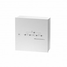


The EBM-10/31-WTL-1T external bypass module is used together with ST3110L and ST3110SL UPS models with a 3:1 configuration, floor-standing, with an output power of 10 kVA. The device is designed for manual, uninterrupted transfer of power for connected equipment from the UPS to the input mains for configuration, servicing or replacement of the uninterruptible power supply.
The module is mounted on any flat vertical surface.
The EBM-10/31-WTL-1T is designed specifically for UPSs with a three-phase input and a single-phase output, equipped with a separate input for connecting bypass circuits, and has two independent inputs for connecting external power sources (see diagrams below): 'Mains 1' is connected to the power circuit of the UPS automatic electronic bypass, and 'Mains 2' is connected to the power circuit of the UPS rectifiers. If there is no need to connect two external power sources, a jumper link L1-L1 is installed between the inputs.
Operating modes
The EBM-10/31-WTL-1T has three operating modes, each characterised by a specific state of contacts S1, S2, S3 and S4:
- UPS mode (main) – the load is connected to the UPS output, the UPS power circuits are connected to supply mains Mains 1 and Mains 2 (contacts S1, S2, S4 closed, S2 open) This is the main mode: the load is powered by the UPS inverter; in the event of an inverter fault or overload, the internal electronic automatic bypass transfers the load to Mains 1.
- SERVICE mode – the load is connected to the bypass mains of the external bypass module, the UPS output is disconnected, the UPS power circuits are connected to supply mains Mains 1 and Mains 2. The UPS runs at no load (contacts S1, S2, S3 closed, S4 open): Service mode is used for scheduled UPS maintenance as well as for commissioning.
- BYPASS mode – the load is connected to the bypass mains of the external bypass module, the UPS output is disconnected, the UPS power circuits are disconnected from the supply mains. The UPS is completely de-energised (contact S3 closed, S1, S2 and S4 open): Bypass mode is used to replace current-carrying components or a faulty UPS.
Connection
Input connections are made via terminal connections. One power input.
Connection to the UPS is also made via terminal connections.
For output connections, circuit breakers 1×C40, 1×C32, 1×C20, 3×C10, 2×C6 are provided.
A terminal block is provided for connecting the charger or service loads.
Control and indication
The front side of the module has:
- bypass block diagram with LED indication showing the presence of voltage in the circuits;
- cam switch handle for convenient switching of the device operating modes.
- Specifications